The post describes a MATLAB script for writing ABAQUS hexahedral finite element mesh and Euler angles from synthetic microstructures generated in Dream.3D.
Intro
One of the great features of Dream.3D is the generation of synthetic microstructures. It allows for virtual experiments with 3D microstructures as well as for studying the effects of various microstructural features on the full-field stress–strain distributions or effective mechanical characteristics of representative volume elements.
To facilitate such micromechanical studies, Dream.3D (starting from ver. 6.1.77) introduced a filter called Abaqus Hexahedron Writer, which writes a set of ABAQUS input files containing a mesh of eight-node brick elements grouped in Element Sets (and Sections for assignment of material properties) that represent grains (“Features” in Dream.3D terminology).
Until now, however, Abaqus Hexahedron Writer filter does not allow for export of grain orientations along with the ABAQUS input files. This post describes a work-around for writing grain orientations to a text file in addition to ABAQUS hexahedral mesh.
Workflow
The workflow suggested here is very simple:
- Generate your synthetic microstructure in Dream.3D
- Write microstructure information as a grid of voxels to a text file (Write Los Alamos FFT file filter)
- Use my
dream2abahexMATLAB script to write mesh file and grain orientations file based on the information in the Los Alamos FFT file.
At the core of this work-around is a custom MATLAB script called dream2abahex. This script writes coordinates of eight nodes around each voxel in the Los Alamos FFT grid and writes instructions how these nodes should be connected to form eight-node brick (C3D8) elements. Furthermore, the script preserves the information about grain IDs using Element Sets and phase IDs using both Element Sets and Sections. The choice to pass phases (rather than grains) as Sections is associated with the expectation that material properties will vary from phase to phase rather than from grain to grain.
Tip: it is quite straightforward to change this choice if your user material subroutine supposes that material properties differ from grain to grain and thus requires an individual Section for each grain.
Finally, and most importantly, the script writes Euler angles (which were read from the FFT file) for each element as a look-up table to a new text file. These orientations can be read from FORTRAN user subroutine defining the behavior of the material (e.g. UMAT).
Tip: as a bonus, the script creates Sets of nodes laying on all 6 faces of the representative volume so that Boundary Conditions can be readily defined on these nodes. Created Node Sets are named according to the face normals, e.g. nodes laying on the face whose normal is +X are contained in Node Set called “NODES+1”, nodes laying on the face whose normal is -Z is contained in “NODES-3”, etc.
Usage
Download dream2abahex script from GitHub, place it to a folder known to MATLAB and run
dream2abahex('path/to/fft/micro.vox', 'desired/path/to/abaqus/file/aba.inp')This function call will result in creating a file aba.inp containing the mesh and aba.tex containing the orientations of each element.
Example
Let’s generate a synthetic microstructure using statistics for a two-phase microstructure consisting of a primary phase and second-phase particles. For this purpose, we can use a prebuilt pipeline called Two Phase Cubic Hexagonal Particles Equiaxed (comes with Dream.3D ver. 6.2.0) that uses statistics file TwoPhaseCubicHexParticlesEquiaxed.dream3d. To this pipeline, we shall only add Write Los Alamos FFT file filter to write the voxel file (e.g. 2ph_64x64x64.vox) from which we will create our mesh.
After the pipeline is successfully completed, we run the MATLAB script pointing to our Los Alamos FFT grid file and giving a name for ABAQUS input file by the following command
dream2abahex('2ph_64x64x64.vox', '2ph_64x64x64.inp')Tip: if 2ph_64x64x64.vox is not in MATLAB path, use the full path of the grid file, e.g. `C:\Users\UserName\Documents\2ph_64x64x64.vox’ as input to the function. Full path can also be used for the resulting mesh file. File with Euler angles will always be written to the same folder as the mesh file and will have the same name with extension .tex
As a result, we obtain an ABAQUS input file (2ph_64x64x64.inp) containing a C3D8 (brick) mesh with grains saved as Element Sets and phases saved as both Sets and Sections. In addition, we get a text file (2ph_64x64x64.tex) with grain orientations (represented by Bunge Euler angles) for each element in the mesh with orientations sorted according to the element label. An example of the contents of the file with grain orientations is below
# Euler angle sets (phi1, Phi, phi2) for C3D8 mesh in 2ph_64x64x64.inp
# Euler angle sets are sorted according to element labels
# 1 element in mesh - 1 set of Euler angles. Generated by dream2abahex.m
B	262144
      17.0020     115.9040    -108.5220    # -----> for element 1
      17.0020     115.9040    -108.5220    # -----> for element 2
	....
    -105.7370      51.4060    -151.4460    # -----> for element n
    -105.7370      51.4060    -151.4460    # -----> for element ...
    -105.7370      51.4060    -151.4460    # -----> for element 262144
It is seen that the orientation file has three information lines followed by a line containing Euler angles convention (B is for Bunge) and the total number of orientations in the file. Then, there are sets of three float numbers correponding to the three Euler angles – , , .
Now let’s check if the Sections and Element Sets correctly represent the original phases and grains.
Below is the comparison between the original phase IDs from dream3d file and the sections in the generated mesh.

The distribution of phases looks identical in both figures. Next we compare the original grain IDs in dream3d file and Element Sets in the generated mesh.
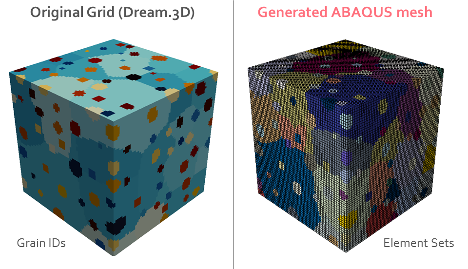
Looks alright.
As a final note, we should remember that the phases are passed to the ABAQUS model as Sections with assigned properties and they suppose that the model will contain the same number of Materials. Therefore, Materials named ‘Phase-1’, ‘Phase-2’, etc. must be defined for running the simulation.